Contents MicroPython is a version of Python 3 which runs on microcontrollers.
I use it on a pyboard for hands-on lab sessions in a computer architecture course (in French). It is like an Arduino on steroids, with an embedded Python 3 interpreter, which makes it very suitable for teaching in French “grandes écoles” since all students in prep classes now use Python in their “computer science” course.
I now also use it on an ESP32 for personal and student projects. The big advantage of the ESP32 is that it has WiFi and Bluetooth and that it is really cheap!
Note: I have written a tutorial (in French) for my students who begin with the pyboard or the ESP32.
Github repositories
My Micropython development tools
Using the pyboard
The case of Windows 10
I do not use Windows regularly, but from what I checked to be able to help students with Windows 10 machines, it seems that there is no need to install a driver for using the pyboard, Windows 10 mapped the USB serial connection of the Pyboard to COM3 on my virtual Windows machine without me doing anything special. The easiest solution to program MicroPython devices seems to be the Pymakr plug-in in Visual Studio Code. This may also be true on other platforms such as Linux and MacOS
When plugged into a USB port of a computer, the pyboard appears as a disk. You can edit the main.py file on this disk, then eject it, and press the RST button on the pyboard to reboot it and execute main.py.
However, there is a more interactive way of playing with the pyboard which has a REPL (Read-Eval-Print Loop). For this, you need to connect to the /dev/ttyACM0 (Linux) or /dev/tty.usbmodemXXXX (MacOS) using a serial communication program. The Unix screen command works fine, I used minicom for a while, but it does not seem to work with some ESP32 cards with MicroPython, so I switched to picocom. There are specific instructions for using the pyboard with Windows.
The tools presented here are available on:
https://github.com/Frederic-soft/Micropython
Pyterm Pyterm
The following script, which I use to call pyterm, will look for a plugged pyboard or ESP32 board and connect to the first one it finds using picocom:
#!/usr/bin/env python3
#!/usr/bin/env python3
import sys
import os
import serial.tools.list_ports

"""
Usage: pyterm [device]
Calls picocom on "device". If device is not given, looks for Micropython or openMV
devices and pick the first one (but print all devices found).
"""
def main():
  if len(sys.argv) > 1:
    pyports = [serial.tools.list_ports_common.ListPortInfo()]
    pyports[0].device = sys.argv[1]
  else:
    ports = serial.tools.list_ports.comports()
    pyports = []
    for p in ports :
      if p.manufacturer in ['Micro Python', 'MicroPython', 'OpenMV'] \
      or 'USB to UART' in p.description :
        pyports.append(p)
    if len(pyports) == 0 :
      print("No MicroPython device found")
      for p in ports :
        print("  " + p.device
            + " - " + (p.manufacturer if p.manufacturer is not None
                                      else "No manufacturer")
            + " / "
            + (p.description if p.description is not None
                             else "No description")
        )
      sys.exit(1)
    if len(pyports) > 1 :
      print("MicroPython devices found:")
      for p in pyports :
        print("  " + p.device + " - " + p.description)
# os.system('minicom -D '+pyports[0].device)
  os.system('picocom '+pyports[0].device+' -b115200')

if __name__ == "__main__":
    main()
Once connected, you can type Python commands and discover many possibilities of the pyboard. For instance:
led = pyb.LED(1)
led.on()
will turn on the red LED on the pyboard.
led = pyb.LED(1)
def blink(timer):
  led.toggle()
tim = pyb.Timer(4, freq=2, callback=blink)
will make the red LED blink at 1Hz (it is toggled on/off at 2Hz).
To close the connection and exit type:
Ctrl-Afollowed byXwith minicom (it isESCfollowed byXon MacOS)Ctrl-Afollowed byCtrl-Xwith picocom.Ctrl-Afollowed by:quitwith screen.
You may also use the miniterm.py command that comes with pySerial. The default exit character is Ctrl-], which you cannot type on a French keyboard, so use miniterm.py --exit-char 0 to be able to exit with Ctrl-@.
You will find more information about what you can do with the pyboard in the MicroPython tutorial.
Loading code into the pyboard Loading code
For writing more complex code, there are two possibilities:
- edit the files on the pyboard, and load them into the REPL using
import - edit the files on your computer, and paste them into the REPL
The first solution works fine and is the only way to work with code that is split into different modules.
The second solution is perhaps easier, but you cannot paste too much text in the REPL without getting errors. You have to switch to the raw REPL by hitting Ctrl-A, pasting your code, and hitting Ctrl-D to finish the transfer. Your code will be running on the pyboard. Hit Ctrl-C to kill it if it does not terminate by itself, then hit Ctrl-B to exit the raw REPL and switch back to the friendly REPL. You can perform a soft reset of the pyboard by hitting Ctrl-D.
Note than when using minicom or picocom, you have to hit Ctrl-A twice to send a Ctrl-A to the REPL because Ctrl-A is by default the escape key of minicom and picocom. You can use the paste file command in minicom to send a file to the REPL. For this:
- hit
Ctrl-Atwice to enter the raw REPL - hit
Ctrl-A Yto execute the paste file minicom command - navigate to your file in the file selection screen that appears and select it
- hit
Ctrl-Dto finish the transfer
Your file is then loaded. If it contains just definitions, hit Ctrl-B to exit the rawREPL and use the definitions in the regular REPL.
Pyboard.py
Another way of executing code on the pyboard is to use the pyboard.py script available in the tools directory of the MicroPython git repository. Exit pyterm, then load your file onto the pyboard with pyboard.py file_to_load.py. You can connect to the REPL again by launching pyterm.
Note that pyboard.py can be installed by installing rshell (see below).
You can use the following pyload script to find the pyboard device automatically and then call pyboard:
#!/usr/bin/env python3
#
import os
import sys
import serial.tools.list_ports

"""
Usage: pyload [--device <device>] file.py
"""
ports = serial.tools.list_ports.comports()
pyports = []
if '--device' in sys.argv :
  cmd = "pyboard " + " ".join('"'+arg+'"' for arg in sys.argv[1:])
else:
  for p in ports :
    if p.manufacturer in ['Micro Python', 'MicroPython', 'OpenMV'] \
    or 'USB to UART' in p.description :
      pyports.append(p)
  if len(pyports) == 0 :
    print("No MicroPython device found")
    for p in ports :
      print("  " + p.device
          + " - " + (p.manufacturer if p.manufacturer is not None
                                    else "No manufacturer")
          + " / "
          + (p.description if p.description is not None
                           else "No description")
      )
    sys.exit(1)
  if len(pyports) > 1 :
    print("MicroPython devices found:")
    for p in pyports :
      print("  " + p.device + " - " + p.description)

  cmd = "pyboard --device " + pyports[0].device + " " + " ".join('"'+arg+'"' for arg in sys.argv[1:])

print(cmd)
os.system(cmd)
rshell
When working with an ESP32, which does not mount its file system on your computer, it main be easier to work with rshell by Dave Hylands.
rshell is easy to install: pip3 install rshell (you may need to sudo this).
In order to avoid to look for the right device in order to connect to your board, I have written a pyrshell wrapper around rshell, which will invoke rshell on the first Micropython board it finds. If no board was found, it will display the list of communication ports found so that you can look for a new kind of board that was not recognized. Currently, the recognized board are the pyboard, the ESP32 and the OpenMV Cam H7 board.
If several Micropython board were found, the first one will be chosen, but the list will be displayed so that you can choose a specific board if needed.
Code samples
Here are some code samples that work on the pyboard. I give them here, hoping they can be useful to someone, but there is no guaranty about their correctness or accuracy. I welcome any constructive remark about this code since I am not an expert in Python nor in coding for microcontrollers.
All this code is available on:
- https://github.com/Frederic-soft/pyboard for the Pyboard
- https://github.com/Frederic-soft/ESP32 for the ESP32
Using the MMA7660 accelerometer of the pyboard Accelerometer
The pyboard has a builtin 3 axis accelerometer. You can find how it is interfaced with the pyboard on the schematic view. When powered on, it appears on I2C bus 1, and the documentation of the chip is also available. Although the MicroPython library contains an Accel class to access the data provided by the accelerometer, I have written an MMA7660 class which gives more in-depth control of the chip and allows you to configure it for generating interrupts.
As an example, here is how you can code a spirit level using this module and an 8x8 LED matrix (see below for the module used to drive the matrix):
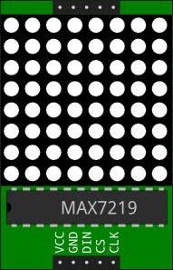
Using a MAX7219 to drive LED displays MAX7219
The MAX7219 provides a serial interface for driving LED displays with up to 8 7-segment digits, or 8x8 LED matrices. Here is a MAX7219 module to communicate with a MAX7219 and display digits or control individual segments.
Built on this module, a LEDMatrixWithMAX module is also available for controlling an 8x8 LED matrix, addressing individual pixels and even displaying pictures.
Using a HT16K33 to drive LED displays HT16K33
The 7-segment display with backpack by Adafruit uses an HT16K33 to control the display through an I2C interface. Here is a module to use it with the pyboard.
Using AdaFruit Motor shield V2 to drive motors Motor shield
The Arduino motor shield V2 by Adafruit can be used with the pyboard to control DC motors, stepper motors and servo motors. I have written two modules to interface with the PCA9685 chip on the shield and drive different kinds of motors. I use the four PWM pins that are not used by the M1, M2, m3 and M4 ports (PWM outputs 0, 1, 14 and 15) to drive servo motors. See the details and get the code on my github repository.
Firmware update
In order to update the firmware of the pyboard, you must place it into DFU (Device Firmware Update) mode. For this, disconnect everything from the pyboard, connect the DFU pin to the 3V3 pin (they are next to the X16 and X17 pins), and connect your pyboard to your computer with a USB cable.
The latest firmware for your pyboard can be found at http://micropython.org/download/.
To upload it to the pyboard, you need a DFU utility. You can use dfu-util:
sudo dfu-util --alt 0 -D <firmware.dfu>
or the pydfu Python script:
python pydfu.py -u <firmware.dfu>
where <firmware.dfu> is the exact name of the firmware you want to put on the pyboard.
pydfu.py relies on libusb and the PyUSB module.
Detailed instructions can be found on https://github.com/micropython/micropython/wiki/Pyboard-Firmware-Update.
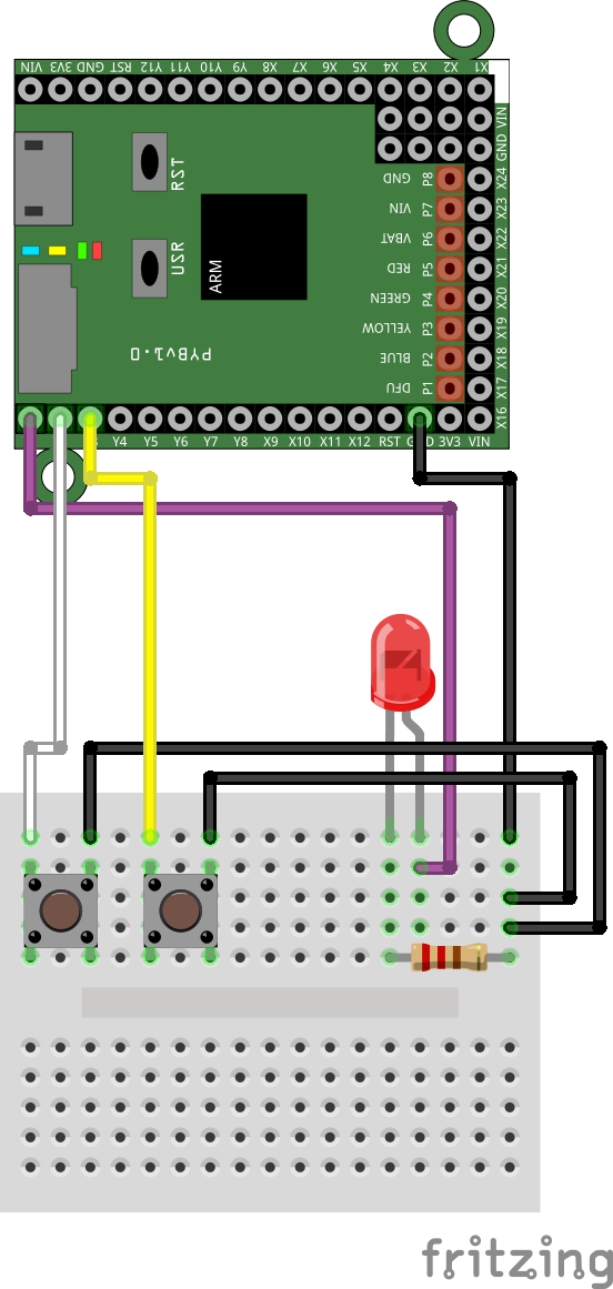
Fritzing parts
I use Fritzing to draw my sketches. I have made a Fritzing part for the pyboard. You can also get the SVG pictures I made for the PCB, the schematics and the icon.
You can see how it looks on the example below:
I have also made a Fritzing part for an 8x8 red LED matrix with a MAX7219: RedLEDmatrixWithMAX.fzpz. The SVG pictures for the breadboard, PCD and icon, and for the schematic are also available: RedLEDmatrixWithMAX7219.svg and RedLEDmatrixWithMAX7219_schematic.svg.