Contents
Connection
The motor shield V2 by Adafruit can be used with the pyboard thanks to its I2C interface. There are two possible I2C buses on the pyboard: I2C bus 1 has SCL on pin X9 and SDA on pin X10, I2C bus 2 has SCL on pin Y9 and SDA on pin Y10.
The following picture shows how to connect the motor shield to a pyboard using I2C bus 1:
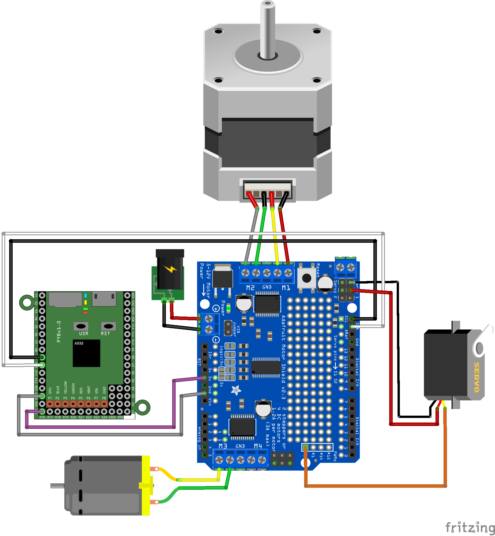
This configuration requires an external power supply for the motors. With small motors, you can use the 5V power supply of the pyboard by installing the VIN jumper on the shield and connecting the other VIN pin of the pyboard to the Vin pin of the shield. Be sure not to connect a power supply to the shield when you do this. If you see the green LED on the shield blink when you drive a motor, this means that the motor draws too much current for the pyboard. In this case, remove the wire that connects the two VIN pins and the jumper, then plug an external power supply.
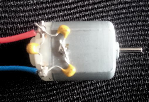
If you get errors or erratic behavior when driving a DC motor, this may be caused by the noise generated by the brushes in the DC motor. You can solder three 100nF capacitors on the motor to filter this noise out: one between the terminals of the motor, and one between each terminal and the case of the motor as shown below.
Module adamotshv2fb
The adamotshv2fb module provides an interface to the motor shield. It contains several classes for driving DC motors, stepper motors and servo motors. You will also need module pca9685fb to create the PCA9685 object which controls the PWM channels.
class DCMotor
This class is for driving DC motors in both directions at different speeds.
DCMotor(pca, motor)- create an interface to a DC motor connected to port
motor.
The shield has four motor ports M1, M2, M3 and M4.motoris therefore 1, 2, 3, or 4.pcais a PCA9685 object that you should have created beforehand. throttle(th)- set the throttle for the motor.
this between -4096 and 4096.
Negative values make the motor run in the reverse direction.
The absolute value ofthis 0 for stopping the motor up to 4096 for making it run at full speed. brake()- actively stop the motor. This stops the rotation of the motor faster than just setting the throttle to 0.
class Stepper
This class is for controlling stepper motors. See Adafruit detailed documentation or MC Hobby's wiki (in French) to find out how to connect a stepper motor to the shield.
Stepper(pca, stepper)- create an interface to a stepper motor connected on port
stepper.stepperis either 1 (corresponding to ports M1 and M2) or 2 (corresponding to ports M3 and M4).pcais a PCA9685 object that you should have created beforehand. fullStep(n, delay=10)- make the stepper perform
nfull steps, with a delay ofdelayms between each step. Ifnis negative, the motor will turn in the opposite direction. waveStep(n, delay=20)- same as
fullStep, but with only one coil energized at a time. This provides less torque but draws less current. halfStep(n, delay=10)- make the stepper perform
nhalf steps, with a delay ofdelayms between each step. Ifnis negative, the motor will turn in the opposite direction. Half steps are obtained by alternatively powering 1 and 2 coils. A full turn will need twice as many steps than withwaveSteporfullStep. microStep(n, delay=1)- make the stepper perform
nmicro steps, with a delay ofdelayms between each step. Ifnis negative, the motor will turn in the opposite direction. Micro steps are obtained by powering the coils with a better approximation of a sine curve. The default is to use 16 microsteps, but you can change this value to 8 or 32. You must reload the module if you change this value because the table that contains the approximate sine wave for each micro step is computed when the module is loaded. A full turn will need 16 times as many steps as withfullStep.
class Servo
This class is for controlling a servo motor connected to one of the four remaining PWM outputs (0, 1, 14 and 15) of the PCA9685 that are not used by the M1, M2, M3 and M4 motor ports. Note that this is completely different from the Servo class of the Arduino library, which uses the timers of the Arduino. You can reuse the two alimentation pins available on the servo connectors of the shield, but you will have to plug the control pin of the servo on one of the PWM outputs of the PCA9685 (see the picture at the top of this page).
Servo(pca, pwm, min_us = 500, max_us = 2500, range = 180)- initialize a Servo object to control a servo motor controlled by PWM output
pwm, which should be 0, 1, 14 or 15.pcais a PCA9685 object that you should have created beforehand.min_usis the shortest pulse width in µs for your servo motor.max_usis the longest pulse width in µs for your servo motor.rangeis the rotation range of your servo in degrees. setDutyTime(us)- set the duty time (pulse width) in µs. Useful for experimenting with a servo and finding the min and max pulse widths.
position(degrees)- set the position of the servo in degrees.
0 corresponds to the minimal position,range, as set when creating the object, corresponds to the maximal position. release()- release the servo motor by setting the pulse width to 0.
Note that the default PWM frequency of 200Hz is generally too high for servo motors. I obtained better results with a frequency of 50Hz, using pca.setFreq(50). Servo objects should be created after setting the PWM frequency of the PCA9685 because the conversion between microseconds and duty cycles is computed at the creation of the Servo.
Example
Here is a small example of code for controlling a DC motor, a stepper motor and a servo motor in the configuration shown in the picture above.
Module pca9685fb
The pca9685fb module provides an interface to the PCA9685 chip on the motor shield. It contains class PCA9685, with the following methods:
PCA9685(i2c_bus, address = 0x60)- create an object for interfacing with a PCA9685 chip at a given address on an I2C bus.
i2c_busmay be 1 (SCL on pin X9 and SDA on pin X10) or 2 (SCL on pin Y9 and SDA on pin Y10). The address defaults to 0x60, which is the default address of the chip on the motor shield. You may use several shields on the same bus by soldering the jumpers next to the VIN jumper to set different addresses. See Adafruit detailed documentation or MC Hobby's wiki (in French) for more details, as well as the datasheet of the PCA9685. start()- start the PWM timers of the PCA9685.
stop()- stop all PWM channels and then stop the internal clock of the PCA9685.
sleep()- stop the internal clock of the PCA9685, making it ready to restart later.
restart()- restart the internal clock of the PCA9685, restoring all PWM settings.
reset()- reset all PCA9685 chips connected to the I2C bus.
getFreq()- get the PWM frequency in Hz.
setFreq(freq)- set the PWM frequency in Hz (minimum is 24Hz, maximum is 1526Hz).
setDuty(channel, rate)- set the duty rate of a channel. The PCA9685 has 16 PWM channels, numbered from 0 to 15. The rate is between 0 (meaning completely off) and 4096 (meaning completely on). In between, the PWM signal will start at step 0 and end at step
rate, each period being divided into 4096 steps. setDutyPct(channel, pct)- set the duty cycle in percents. 0 percent means off, 100 percents means on.
setPWM(channel, on, off)- set the PWM parameters for a channel.
onis the starting step of the PWM signal,offis the stopping step. Both values are between 0 and 4096. 4096 foronmeans always on. 4096 foroffmeans always off. getPWM(channel)- return a pair containing the on and off timing values for a PWM channel.
Example